Get your science in Shape

3-D Module
Basic workflow:
Interactively add the geometric elements of your object in the form of primitive polygon meshes (Primitives) that you can access at the top menu bar of the 3-D Module. These meshes will serve to encase the volumes that will constitute the different parts of the model. Then you modify the simple structure of the Primitives using what we call Modifiers, which give the objects new geometric structure and physical properties as a function of position in space. Using the Physics Module, you then assign the material and radiation properties to the meshes. Finally, the model is rendered with the Render Module and some of the observational properties can be displayed with the (Channel) Maps and Graph Modules, where the observational data can be included and compared with the model results. If the results are not satisfactory, the model will be adjusted until a satisfactory match is found between observations and model.
Overview of the 3D Module:
The purpose of the 3D Module is to set up your model interactively.
This module is divided in several sections, the interactive 3-D view ports, the Menu Bar at the top, Objects, Tools & Lights tabs on the right and Transform Tools on the left.
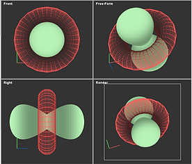
3-D view ports:
By default there are four view ports that can simultaneously show you the same number of different views of your mesh model. Several of these camera views are aligned with the coordinate axes (initial defaults: Front, Right). The Free-Form view can be changed arbitrarily using mouse input after selecting the Camera > Orbit tool from the Transform Tools to the left of the 3-D view ports (see Transform Tools for details). A special view port is the Render view, since it represents the view that will be used for rendering in the Render Module. This view can be controlled interactively with the Mouse in the same way as the Free-Form view, but also numerically with Image and Camera parameters in the Render Module.
Right-click menu:
When you right-click on the area of a 3-D viewport, a menu opens that allows you to set a number of properties of this particular view.
Camera:
Select a different camera view for this viewport.
Save Image:
Save the mesh images of the viewports. It saves the image of all viewports in one image. If you want to save only a single view, then use the Maximize command from the right-click menu to open a single view in the 3-D view space (to go back to the four viewports, right-click again and select Restore). Make sure to provide a filename with a valid image extension. Most common image formats are supported, such as .png (recommended), .jpg, .gif, etc. (example: image1.png). The Save Image function is the same as that of the Save button in the 3-D Module´s top menu bar.
Saving your viewport images with this function does not include the colored coordinate axes or the viewport labels. To saves these you can make screenshots of these areas.
Properties:
In this dialog you can set a few parameters for the individual view port.
Scene alpha: This parameter changes the transparency of the whole polygon object scene, so a comparison with observations or the rendered scene may be easier with lower alpha values.
Background: This setting selects the background image of the scene between None, Observed and Rendered, which enables you to compared the corresponding images with the mesh. Including the Observed data is useful to place and shape mesh objects according to the observations. Note that a direct comparison with observed data makes only sense for the Render image. Sometimes, comparing the observed images with other views might be helpful when checking for symmetry properties.
Maximize: For more detailed inspection, this command fills the space of the four viewports with a single one. Restore the four views using the Restore command in the right-click menu.
Menu bar:
The Menu Bar of the 3-D Module provides quick access to a number of commands (left section) and the creation of Primitive mesh objects (right section).
Save: Save the mesh images of the viewports. It saves the image of all viewports in one image. If you want to save only a single view, then use the Maximize command from the right-click menu to open a single view in the 3-D view space (to go back to the four viewports, right-click again and select Restore). Make sure to provide a filename with a valid image extension. Most common image formats are supported, such as .png (recommended), .jpg, .gif, etc. (example: image1.png).
Saving your viewport images with this function does not include the colored coordinate axes or the viewport labels. To saves these you can make screenshots of these areas.
Import: This command allows you to import objects from a different project. A file selection dialog opens to select the project from which to import objects. Then a second dialog allows your to select one or more objects (shift-click for selecting multiple objects). Note that it is divided into tabs for different types of objects which have to be imported separately.
Options: The Options dialog contains settings for viewing coordinate grids in the 3-D viewports and other options that might be helpful during modeling and for publication of model meshes.
Undo: This command opens the Undo Stack utility. It shows recent commands that can be undone and redone. You can select which commands to undo or redo and set the maximum number of commands to be held in the stacks. Additional Undo options exist for example for the Path vertex objects which can be undone with Ctrl-z or redone with Ctrl-y.
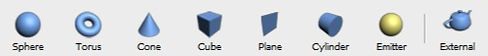
Primitives: The most important functionality of the menu bar in the 3-D Module is to provide quick access to the creation of various Primitives, i.e. basic geometric mesh objects that can be described with only a few parameters.
Create a new primitive object by a first click on the corresponding icon, then click on one of the 3-D viewports and immediate drag the mouse to the right to increase the first parameter of the primitive. When the first size is adequate, click again and drag to the right to increase the second parameter (if necessary). One click and drag to the right for each parameter (sphere has one, cone and plane have two, “cube” has three) of the primitive object and then one more click to finish. Your object appears in the Systems folder of the Objects tab located to the right of the 3-D viewports. By default the names of the objects is PS_#, where # is the number in order of creation. This name can and should be changed to something more descriptive in the General parameters menu of the drop-down list to the right of the Objects folder tree.
The detailed properties of the individual objects can be changed after selecting it by clicking on the objects name in the Objects stack, where it will be highlighted and in the 3-D viewports the corresponding mesh will turn white, if the Show status flag in the General properties is activated (this is the default).
The Object Properties drop-down list contains five different parameter sections:
General, Particles, Modifiers, Primitive and Fields. Click on Object Properties for a link to a more detailed description of its content.
Objects, Tool and Lights tabs:
The parameters of objects and different tools can be set in the Parameter Tabs on the right side of the 3-D Module. There are three tabs available for the parameters.
Objects: handles the parameters of the objects in the 3-D viewports.
Tools: allows access to the parameters of tools such as the Draw Tool or Erase Tool for particles accessed in the corresponding tab on the left of the 3-D Module). The parameters in the Tools tab appear once the tool has been activated.
Lights: change the lighting properties of the 3-D viewports by changing the properties of the default Ambient Light or adding, deleting and changing the positions and parameters of other types of light. A more elaborate lighting scheme is often useful to create schematic illustrations using the mesh objects.

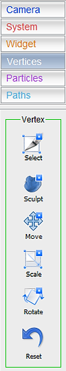
Transform tools:
On the left side of the 3-D Module there is a set of tabs with a variety of tools, most of which interactively change the positions and orientations of various types of helper objects:
Cameras: change the view points of Render or Free-Form view ports interactively.
Systems: change the transform properties of individual objects (Systems) of the scene.
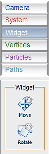
Widgets: change the local coordinate system of the selected tool or modifier.
Vertices: with these tools individual or a group of vertices of meshes are manipulated for very detailed local changes of the meshes.
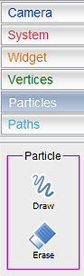
Particles: draw and erase Particles on and around meshes that serve as supports. This allows very detailed structures to be added to an object than can not be easily generated with meshes or procedural filament tools. The parameters of the Draw and Erase particles tools are set in the Tools tab on the right of the 3-D Module.
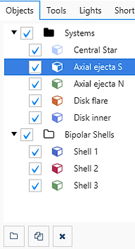
Objects Tree:
The objects tree is a hierarchical list of the current objects in the scene. They can be collected in folders and sub-folder.
With the tick boxes to the left of each object an object can be switched on or off. Similarly switching on or off a folder does the same for all objects in a folder.
New objects are placed in the default "Systems" folder.
New folders are created using the "Add new folder" button at the bottom left.
Copy objects with the copy-button. The copy is then placed at the bottom of the list in the same folder.
Move objects and folders around within the object tree by dragging and dropping.
Delete objects and folder with the delete button at the bottom of the panel.
The color of the symbol to the left of the object name is the same as the mesh color and helps to identify the object in the 3-D views. If the object is not enabled, the color of the symbol is grey.