Get your science in Shape
Key Sub-System: Coordinate Systems
There are several coordinate systems defined in Shape. First of all in most contexts the coordinates may be defined in Cartesian, Spherical or Cylindrical coordinates.
Note that for the spherical coordinates the label convention is that of the North America, with q being longitude and f the latitude.
Hierarchy of coordinate systems:
In addition to the types of coordinate system, there is a hierarchy that determines the origin and orientation of the coordinates.
First there is the global "world" coordinate system that is fixed and everything else is embedded in this system.
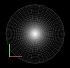
The orientation of the world coordinate system is show by the colored coordinate axes in the lower left corner of the 3D views in the 3D Module (see images on the right). Note that it is not centered on the center of the coordinate system and only provides a visual cue of the orientation. The colors of the xyz axes follow the common order of the color channels rgb (red, green, blue), respectively.
Every object has its own "local" coordinate system, that may move around in the world coordinate system depending on the types of modifier that are applied.
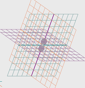
As an illustration compare the two images on the right. In the first one the spherical mesh and the density distribution are centered on the world coordinate system. No changes have been made to any positions.
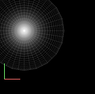
In the second example a Translation Modifier has been applied. It moves the mesh away from the World Origin. Not only the mesh is moved but the density distribution goes along. Similarly, the Rotation Modifier will rotate the density structures along with the mesh, since thee local coordinate system changes.
The translation, rotation and scale operations can be interactively handled using the corresponding Move, Rotate and Size tools in the System tab that is located to the left of teh 3-D views.
It is important to note that, contrary to the Translation and Rotation modifiers, the Size tool and Modifier does NOT change the scaling of the local coordinate system. This would cause too many practical problem during modeling. It only changes the mesh. This is similar to the Displacement modifier which only moves the mesh, not the coordinate system. For rotating only the mesh, operators such as the Twist modifier can be applied.
In third place there is the "widget" coordinate system that is applied to some modifiers. They often need to be centered at different positions within an object, which can be achieved by moving and rotating the coordinate system of the modifier using the Widget tool or Widget dialog. Different modifiers have independent widget coordinate systems. By default modifiers follow the local coordinate system, meaning that their widget coordinates are coincident with the local system until the widgets themselves are changed.
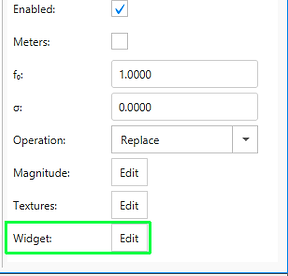
But the coordinate center that a modifier refers to can be changed by changing the widget either interactively with the Widget tool or numerically by opening the Widget dialog from within the modifier panel. To open the Widget dialog click on the Widget Edit button at the bottom of the modifier panel.
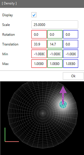
In the image on the right under the widget dialog the object mesh remains at the world origin, while the density distribution is off-center at the position of the widget . The widget itself is represented by arrows. Each modifier may have independent widget, i.e. local coordinate system positions.
In the following image shows the application of the Displacement modifier, which moves only the mesh, not the coordinate system. The mesh container changed position, but the density distribution remained centered on the world coordinates.
An additional fourth coordinate system is that of the observer or camera. These are the coordinates seen in the "shape view port" of the 3D Module and the rendered image in the Rendering Module.
OPERATOR ORDER MATTERS!
In the modifier stack several rotations, translations and other operators can be applied one after the other. The result of such combined operations, in general, strongly depends on the order in which they are executed. Therefore the order of the operator in the modifier stack is very important. For instance, translation can be combined in any order (they are commutative), rotations among themselves and rotations together with translations can not.
Coordinate Display Options Dialog:
The Options Dialog that opens by clicking on the wrench icon on the menu bar of the 3D Module allows you to customize the display of a Cartesian coordinate mesh within the 3D views. It can helps as a reference during the modeling process. An example is show in the bottom image in the column on the right. A little experimentation should clarify the meaning and effect of the various parameters.