
Get your science in Shape
Animation Module

Overview
Most parameters in Shape can be animated over time. This can be used to generate time variation of the models either for scientific modeling of time varying phenomena or for visualization purposes.
A simple example application is the simulation of the lightcurve of an exoplanet or of eclipsing binary stars.
An application that aims more at purely visualization could be rotating the virtual camera around an object go generate a movie that shows the structure as seen from many points of view.
Since animation implies the generation of a large number of individual images that can be joined together in the Movie Module, care needs to be taken in preparation in order for the rendering process to not take an unacceptably large amount of time.

The key question is which type of rendering do you need:
Camera motion: If you animation will consist of camera motion only and the spatial resolution that you need is small enough to allow you to use the grid renderer, then you can save a lot of time. In this case the steps before the final ray casting to determine the image pixel values can then be precalculated and saved. Then they do not need to be repeated for every frame.
Another option to get a camera animation is to use the interactive iluvia software from ilumbra.com . Using the Export Module in Shape you can quickly output your model in a format suitable for iluvia and inspect your model interactively or very quickly set up and capture animations.
Varying model parameters: If parameters of the model itself need to be changed over time, then the precomputed grid changes and a full render is needed for every frame. For complex models and high resolutions, this may take a lot of time to compute, depending on your computing equipment.
Once you decided which type of animation and spatial resolution you need, you can time the rendering and estimate the total time it will take to render the necessary number of frames. For each rendering, come basic stats are output in the Info Module that include the time it took to render. This information can be used to estimate the total time necessary to render out the full animation.
General workflow:
1. Set up the timing and output parameters in the Parameters Panel on the right.
2. Select variables to be animated from the Parameter Tree. They appear in the Animation Parameter Stack.
3. Select each animated parameter in the Animation Parameter Stack and set up its animation graph as a function of time
4. Render the animation
Animation Module UI:
The Animation Module is divided into five main sections. A control bar is at the top and the parameter tree and the animation parameter stack are on the left. In the middle you find the animation graph for the animated parameters. At the bottom is the time line. Finally, the General and Output parameters are in the panels on the right.
Control Bar:
Animate: Starts the rendering of an animation. After each rendered image it advances one frame and renders again.
Refresh: Updates the Parameter Tree after new renderable parameters have been added somewhere in Shape. This does not happen automatically, so make sure to click on this button to see any new parameters.

Up & Down: In the Animation Parameter Stack move selected parameters up or down. This has no effect on the result but is helpful to keep order in the stack when a large number of parameters is animated.
Remove: Removes selected parameters from the Animation Parameter Stack.
Copy & Paste: Copy the animation graph from a selected animation variable in the Animation Variable Stack and paste it to another that you select after copying the previously selected graph.
Parameter Tree:
The parameter tree is a hierarchical list of all animatable parameters.
The parameters may be from the UI, general project parameters or from particular objects. Additionally global parameters that have been defined in the Math module will also show at the bottom of the parameter tree.
To select a parameter for animation, open the parent branches in which it is located. Once the parameter appears, double click on the tick box to the left of the parameter name. When the tick mark is on, the parameter appears in the Animated Parameter Stack, where the time variation of the parameter is set up (see below).
Note that newly created parameters or objects do not automatically show in the parameter tree. To have them appear click on the Refresh button in the menu bar at the top of the Animation Module.

Animated Parameter Stack:
The Animated Parameter Stack is the list of parameters that are selected from the Parameter Tree to be changed, i.e. animated over time.
The first column shows the Parent branch in the Parameter Tree, the second is the name of the parameter. The third column contains the value of the parameter at the current time of the animation time line.
To select a parameter click on the row for that parameter. Automatically its animation graph will be shown.

Animation Graph (not shown):
In the Animation Graph you set up how the parameter selected in the Animation Parameter Stack changes over time. Note that in this graph the x axis is in units of time as defined in the Parameter Panel on the right (see below), whereas the Time Line at the bottom is in terms of the frame number.
The graph is not shown here. It work the same way as other graphs in Shape. For more information on how to set up a graph see the manual page on Graphs.
Parameter Panel (right side)
General: Timing and frame numbers are set up in this tab.
Name: The base name of for the output frames of the animation
Start Frame: The frame number at which to beginn the animation. It may be necessary to start from a position different from 0 or 1 when an animation was interrupted or if several will be concatenated.
# Frames: The total number of frames for the duration of the animation from the Start Time to the End Time.
Start Time & End Time: in terms of time units (see below) when is the animation meant to start and end.
Time Units: Select the desired time unit from the drop-down list. The default is Years. Make sure the unit in the Variable tab is the same or consistent with the needs for this model. The animated variable that is selected and displayed in the graph uses the units from the Variable tab. Occasionally these units need to be different from each other.
Fields: Include the calculation of field lines, magnetic or velocity.
Distribute: Recompute the distribution of particles for each frame.
Render: Do a full render at each time step. Camera animation with "Autorender" on in the Render Module does not require this, since the model grid does not change and is calculated either before the animation is started or with the first frame. After that autorender is used if the Render flag in the Animation Module is off.

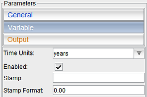
Variable Some control parameters for the animated paramater that is currently selected in the Animated Parameters Stack.
Time Units: The time units to be used for this variable. Make sure it is the same as the Time Unit in the General tab or you are certain of the animation graph in this context of a different general time unit.
Enabled: Enable the animation of this variable. If for some reason you disabled this variable, then later you might wonder why it doesn´t change in an animation. It may well be that you forgot that you disabled it. So, if something in your animation doesn´t change as expected, make sure all the variables that you need change are actually enabled for animation.
Stamp: The total number of frames for the duration of the animation from the Start Time to the End Time.
Stamp Format: The number format for the numerical stamp.
Output: Here you define the output format and what you wish to output and where on disk it is to be placed.
Directory: Set the output directory for the individual animation frames. Note that the name of the files is set in the General Tab.
Image Type: Specify the image type by writing the standard extension for the image. For instance, if you wish to output PNG format images, then write ".png".
3D Mesh: Output and image of the 3D Mesh. Note that it is not the mesh itself that is output, but rather an image of the view in the 3-D Module.
Hydro: Output the full data from the hydrodynamics module at each time step. Note that, depending on the resolution, this might lead to a large amount of data to be output.
Plots (Images): Output images of any graphs that the animation might generate in the Graph Module. You can adjust the image resolution for these outputs.
Plots (Ascii): Output the ASCII values of any graphs that the animation might generate in the Graph Module.
Math Variable: Output any math variables that change over time during the animation.
Stereo: Output stereo images.
dStereo (deg): The parallax anglee. This is the difference between the horizontal camera angles for the two stereo images.
